Robotic Testbed for Research on Dynamic Legged Locomotion on Yielding Terrain
Published:
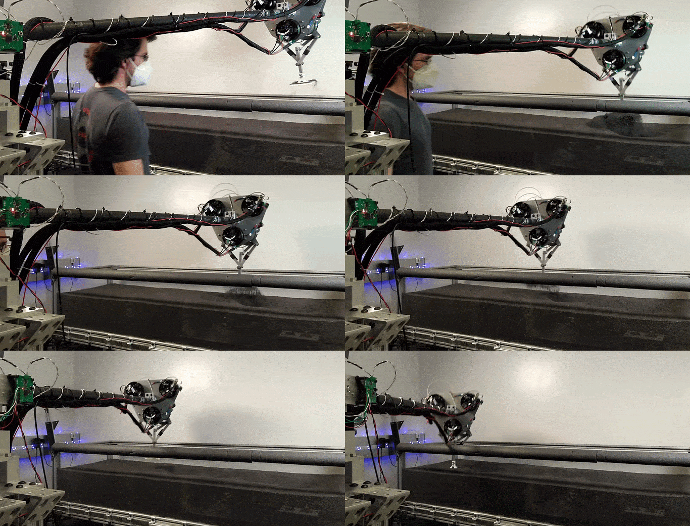
My doctoral research on dynamic legged locomotion on yielding terrain called for a custom robot that could hop in the sagittal plane across a bed of granular media. This robot is a monopod, consisting of a body and a foot, coupled by a planar three-degree-of-freedom linkage actuated by three brushless DC (BLDC) motors. You can see it in action here:
While the research accomplished with this robot is the subject of an upcoming paper (in preparation), this portfolio entry goes into detail on the engineering that went into the robot. The initial design and build took place over six months in 2018, in collaboration with several teammates in Robot Design Studio (a capstone mechanical & electrical engineering course at Northwestern). The mechanical design remained largely unchanged, but I overhauled the electrical system when I started doing experiments with the robot.
Robot Design Principles
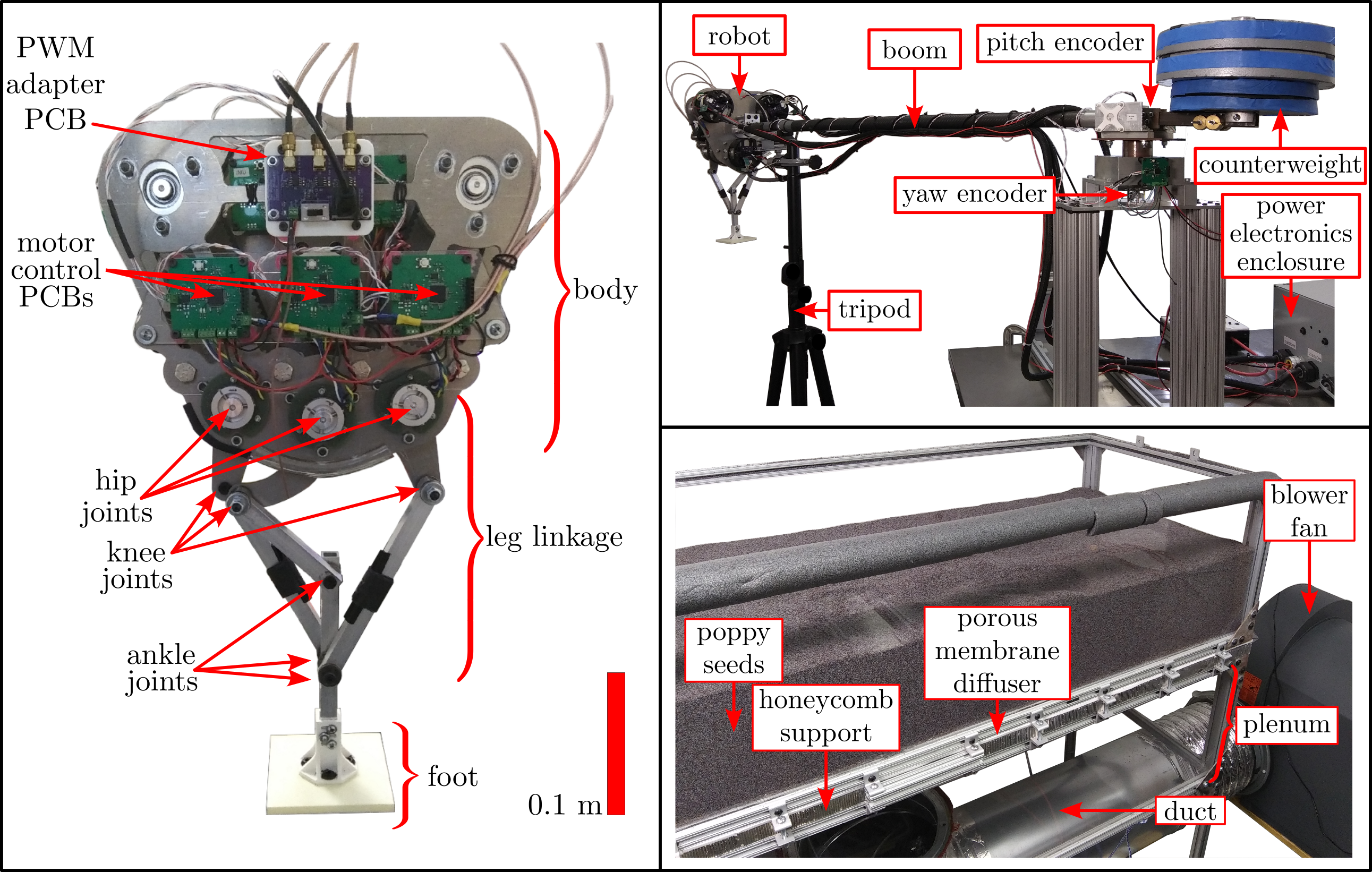
This robot leg design embodies three desirable properties:
- The leg has three planar degrees of freedom (DOF), so the space of feasible planar contact wrenches is full-dimensional.
- The leg is driven by quasidirect-drive actuators, which are highly backdrivable and have low hysterisis, improving the leg’s ability to apply desired contact wrenches.
- The leg’s actuators act in parallel rather than series, reducing the torque required from each actuator as well as the mass/inertia of the linkage connecting the actuators to the foot.
This design cuts down on the inertia of the leg linkage enough that its dynamics can be neglected. Instead of a complicated many-body system, the robot can be modeled as two planar rigid bodies (the body and the foot) connected by an ideal wrench source. The computations required to control the simplified model are, in turn, simpler. which means they can be performed online at a high frequency (1 kHz, in this case).
Robot Body
The robot’s body, shown below in an isometric view, houses the actuators, arranged in a sort of upside-down trianglular fashion.
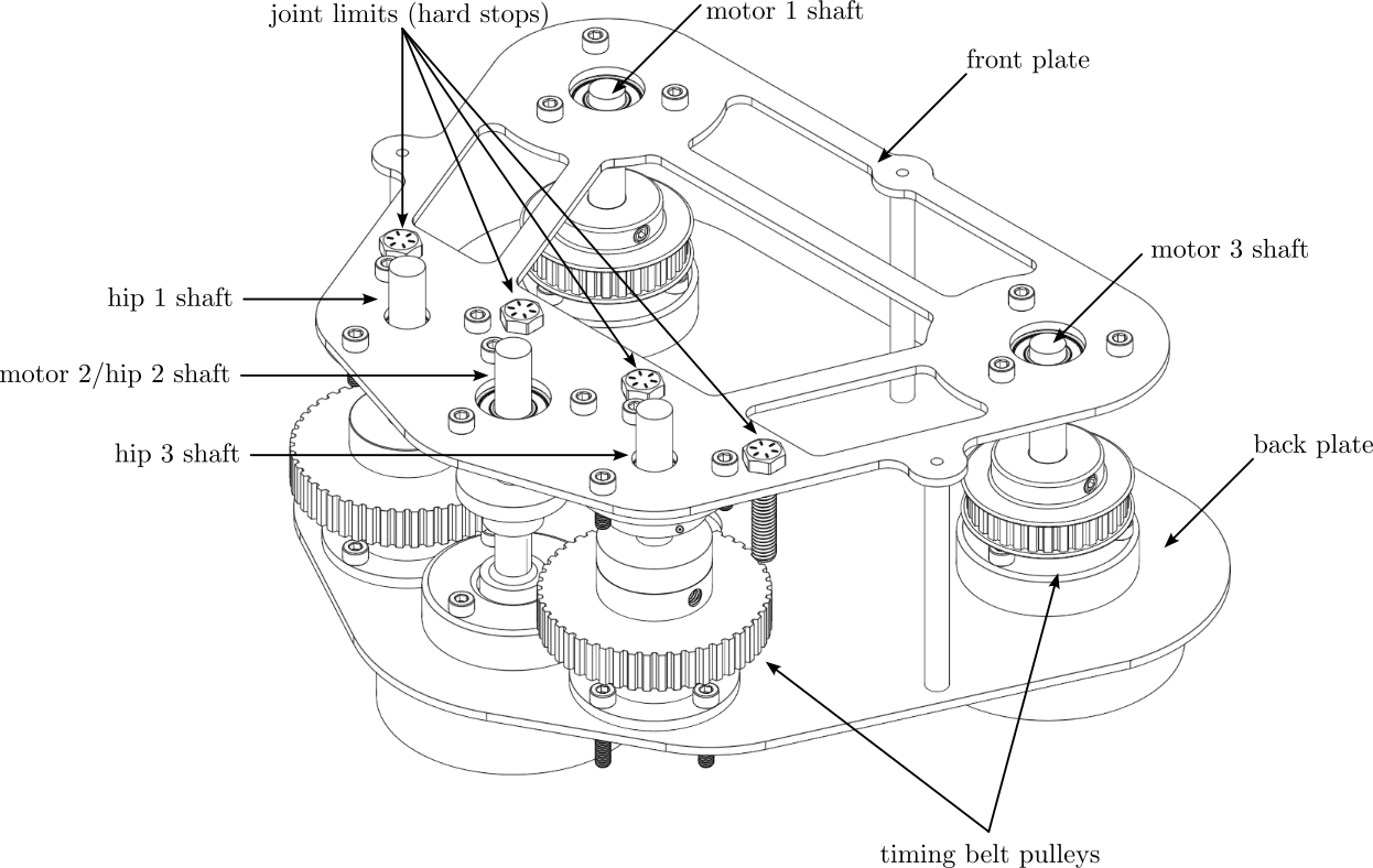
Each actuator is built around a Maxon EC-90 Flat 90 W BLDC motor. A 3:2 gear ratio is used for the left and right actuators and a 1:1 gear ratio for the middle actuator. This “division of labor” works for typical leg configurations and contact wrenches because the torque required at the middle actuator is lower than the torques required at the left and right actuators. These low gear ratios are achieved with timing belts rather than gearboxes, to reduce both mass and backlash. The biggest downside of such low gear ratios is that the motors draw a lot of current (21.1 A at stall!), requiring an appropriately robust system-level electrical design, discussed below.
Boom Subsystem
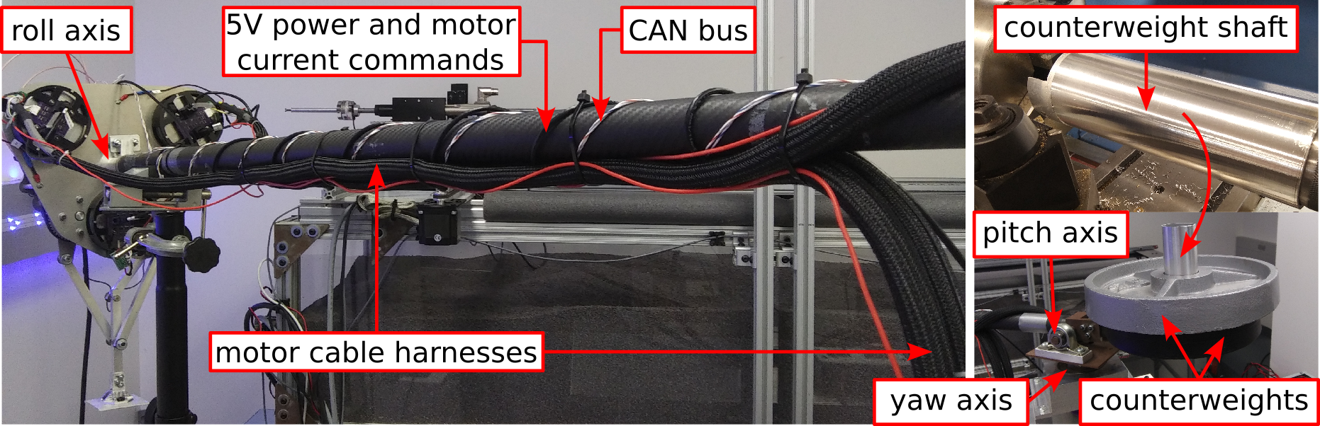
The robot is mounted to the end of a carbon fiber boom so it sweeps out a circle (1.4 m radius) as it hops. This allows the researcher (me!) to focus on hopping and balancing in the sagittal plane without also having to contend with balancing in the out-of-plane direction—the latter increases the difficulty of locomotion without providing much scientific insight beyond what’s already happening in the sagittal plane. The opposite end of the boom has a shaft (like you’d find on a barbell) on which I can load weight plates to reduce the effective gravity the robot experiences, from 1 G to about 1/4 G. This reduces Joule heating at the motor windings (a negative side-effect of the extremely low gear ratio and high torques required to hop), which allows for more hops per experiment and less downtime between experiments. The boom is long enough and the robot hops slowly enough that centripedal forces are small compared to contact forces and the robot’s weight.
Electrical Design
The entire experimental apparatus (control computer, robot leg, boom, and fluidized bed) consists of a number of devices (“nodes”) connected by a Controller Area Network (CAN) bus running at 1 Mbps.
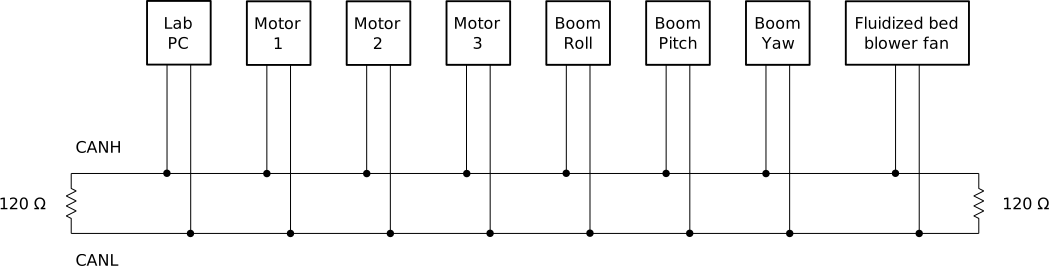
The lab PC, a Linux desktop running Ubuntu, handles high-level trajectory planning and control computations inside a 1 kHz thread and uses a PCIe CAN card to interface with the CAN bus.
The robot leg itself consists of three joint control nodes, one per actuator. The figure below shows the schematic, front (red) and back (blue) PCB layout, and a photo of the joint control PCBs installed on the leg and connected to the joint encoders (below the joint control PCBs).
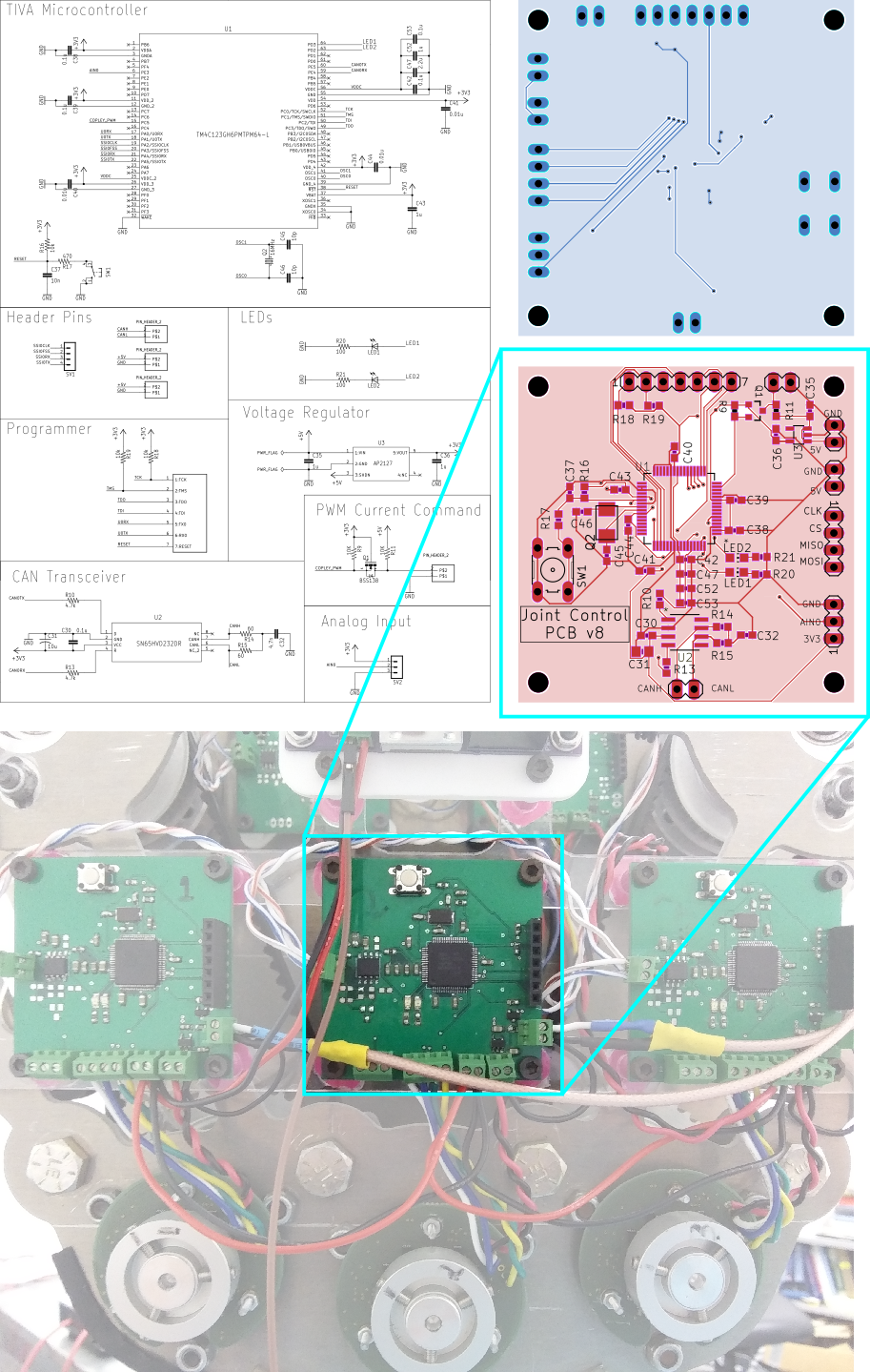
Likewise, the boom also consists of three nodes, one per rotation axis. Finally, the fluidized bed uses one node to interface with the CAN bus. Aside from the lab PC, every other node on the CAN bus is built around a Texas Instruments TM4C123GH6PM ARM Cortex M4 microcontroller with an 80 MHz clock and a variety of peripherals.
Motor Control
There are several commutation schemes for BLDC motors: trapezoidal commutation, sinusoidal commutation, and field-oriented control (FOC). This robot uses FOC because it results in the least torque ripple (a function of motor angle) of the three methods; minimizing torque ripple is important for accurate force control during contact. To do FOC, each motor amplifier (Copley Accelus ASP-090-36) requires an A/B quadrature signal from an encoder on the motor shaft.
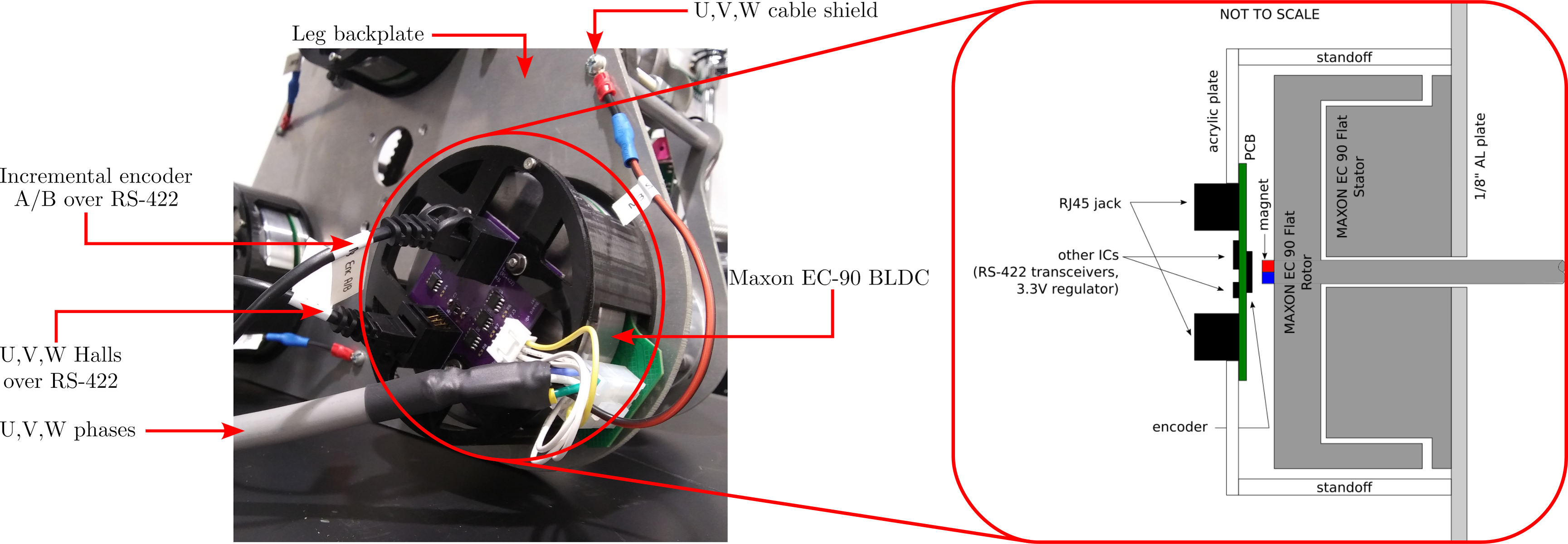
To provide the shaft angle required by the amplifier, I designed and built a small PCB to sit above each motor, measure the shaft angle with a 14-bit magnetic encoder, and turn the single-ended A/B quadrature signals into differential 5 V signals that are sent down the boom to the motor amplifier. The PCB also converts single-ended Hall effect signals from the motor into differential 5 V signals that are sent down the boom to the motor amplifier.
I used a laser cutter and a 3D printer to make a simple lightweight frame that locates the PCB properly above the motor shaft. The entire package (motor, custom PCB, and PLA/acrylic PCB mounting frame) is shown in the picture below.
Mitigating Electromagnetic Interference
All three BLDC commutation schemes use PWM to set the current flowing through each of the three phases (U,V,W) in a BLDC motor. In turn, when the requested phase currents and voltages are high (as is the case for quasidirect-drive actuation), the motor phases radiate a significant amount of electromagnetic interference (EMI), to which the rest of the robot’s electrical system must be robust. This is done in two parts:
- Motor phase cables are shielded, to keep EMI in;
- All logic level signals that run along the boom (alongside the motor phase cables) are differential (RS-422) and are carried by shielded cables, to keep EMI out.
The diagram below shows the combination of shielding and RS-422 transceivers, for a single actuator, used to mitigate EMI. 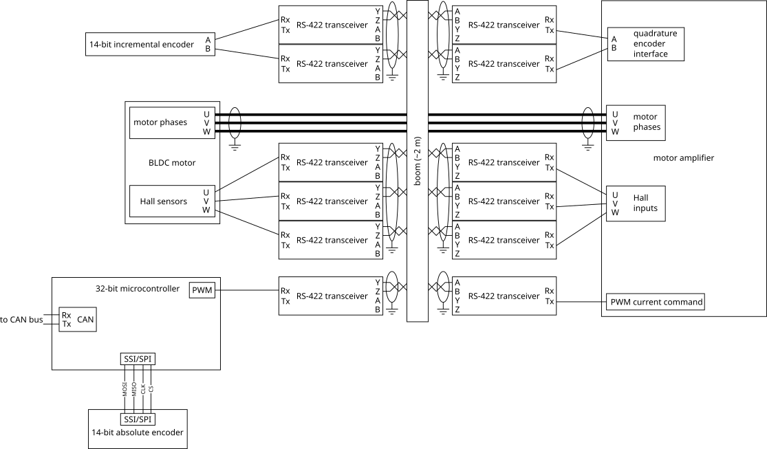
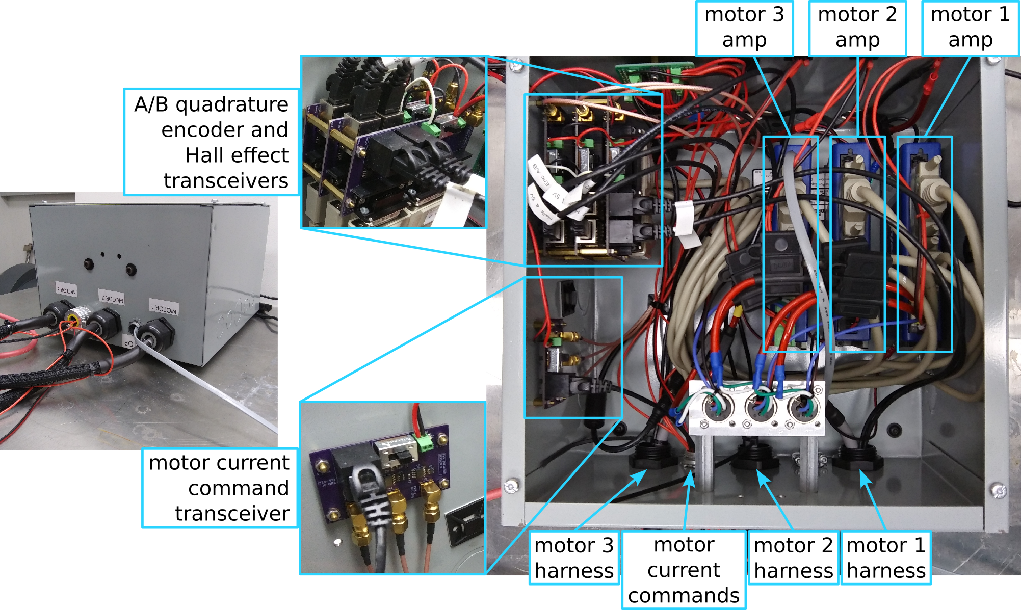
The amplifiers are housed in a steel electrical enclosure, shown below, along with custom RS-422-to-single-ended transceiver PCBs. The steel enclosure further mitigates EMI.